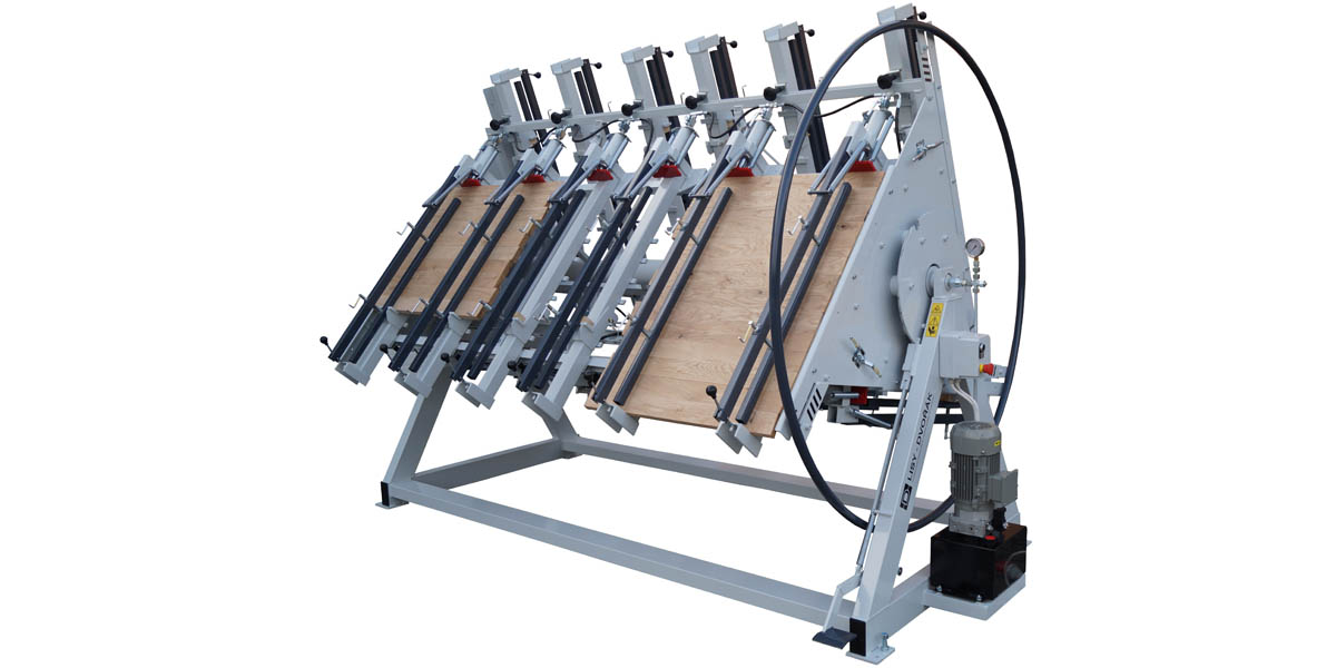
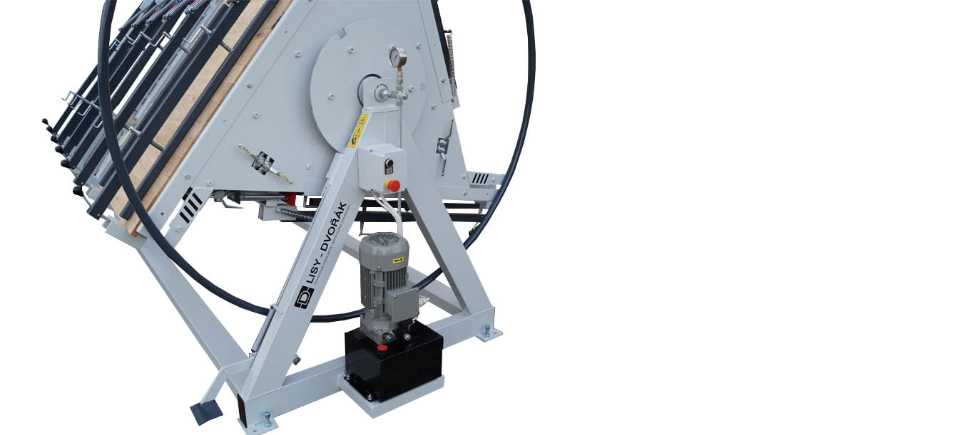
Turnstile press TH3 is determined for edge gluing, especialy for boards and desks. It is welded construction. Triangle rotor which is set up with 3 working tables is installed in bearings on machine fixed frame. In each of 3 working tables there are installed adjustable pressing units with upper clamping beams. Pressing units are moveable in the length axis. Pressing units can be equipped also with adjustable working height supports, so you can set up how wide desk do you want to produce. Source of the pressure is electro-hydraulic pump. Controling of the cylinders is described below. Rotor turning is manual or automatic by electric gearbox.
 | TH3 product leaflet
 | TH3 video
| parameter | value | unit |
|---|---|---|
| machine length | according the working length | mm |
| machine height | 2 350 | mm |
| machine width | 2 350 | mm |
| machine weight | individual | kg |
| number of working tables | 3 | pcs |
| working length | 2 000 - 6 000 | mm |
| working height | 1 050 or 1 250 | mm |
| working height setting | optional (raster 80 mm) | mm |
| max. material thickness (depth) | 50 or 90 | mm |
| number of cylinders | 4 - 14 | pcs |
| cylinder pressure | 2 000 (20) / 4 000 (40) | kg (kN) |
| cylinder stroke | 90 | mm |
| working pressure | 0 - 20 | kg/cm2 |
| hydraulic pump power | 1,5 - 3 | kW |
| hydraulic pressure setting | YES, pressure regulator | |
| maximal pressure in hydraulic circuit | 200 | bar |
| hydraulic oil | HM 46 | 12 liters |
| voltage | 3x 400 V / 50 Hz | |
| prodcutivity | 6 - 9 | tables/hour |
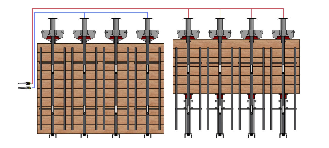
Hydraulic working table control can be done several ways. In basic working table is divided by 2 central stop ball valves into independent 2 halves. If the press is longer there can be 3 central valves and table can be divided into 3 thirds. Next possibility is 1 central stop ball valve and each cylinder extra has got own stop ball valve to be able open or close it. You can set the working zones direcly according your needs this way. Also you can have 2 central valves and each cylinder own stop ball valve. Everything depends on customer needs and his production type. You can see the schemes of different variants of hydraulic circuits below.
2.1 | STANDARD CONTROL 2+2 | There are 2 pcs of central stop ball valves = 2 working zones.
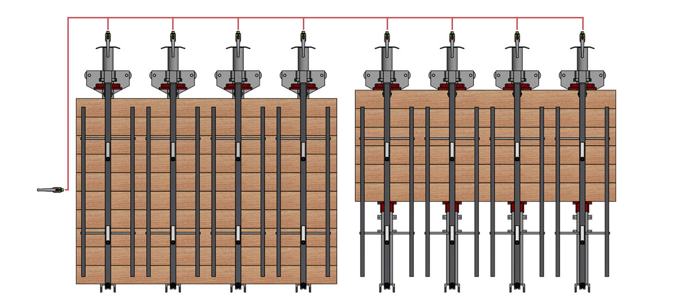
2.2 | 1x CENTRAL + EACH CYLINDER OWN STOP BALL VALVE | There is 1 central stop ball valve and each hydraulic cylinder has got its own stop ball valve, so it is possible to OPEN/CLOSE it separately and use several working zones.
2.3 | 2x CENTRAL + EACH CYLINDER OWN STOP BALL VALVE | There are 2 central stop ball valves and also each hydraulic cylinder has got its own stop ball valve, so it is possible to OPEN/CLOSE it separately and use several working zones.

3.1 | MANUAL HAND WHEEL ROTOR TURNING | Rotor turning is done by hand wheel and position aretation by locking pedal.
3.2 | AUTOMATIC ROTOR TURNING | Rotor turning is done automaticaly by electric gearbox.